2020 wholesale price Trailer Axle Bearings - How to install the air suspension on the axle – MBP
2020 wholesale price Trailer Axle Bearings - How to install the air suspension on the axle – MBP Detail:
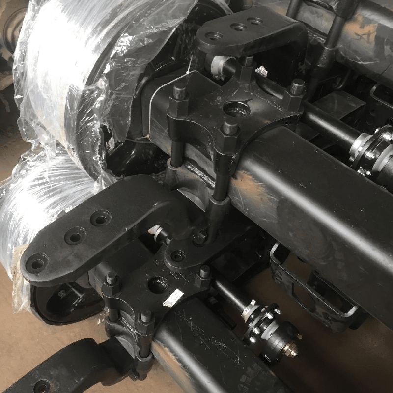
Note: this chapter is mainly describe the installation and welding for over slung air suspension matched with 150 square axle.
1.Installation and welding for leaf spring seat
1.1 Prepare the locating tooling
1.2 Set up the centre distance of leaf spring (spring beam) according to the technical drawing;
1.3 Place the upper plate on the locating tooling;
Notice: the left upper plate and right upper plate can’t be placed oppositely.|
1.4 Place the axle on the upper plate;
Notice: the relative position between mounting holes of camshaft and shock absorber.
1.5 Locating tooling adjust the locating tooling and calibrate the axle position under the requirement: two sides +-1mm.
1.6 Axle fitting welding; connection mode 1: down plate and upper plate; Spot welding the upper plate (this kind of lower support no need welding); Welding the upper plate and axle, with welding height 8mm;
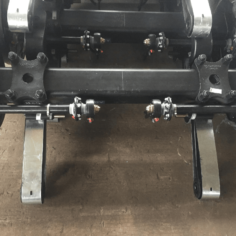
Connection mode 2: down plate and upper plate; Spot welding the upper plate; place the down plate on the axle; connect upper plate and down plate with bolt, then locating; Place the connecting plate between the upper plate and down plate, and spot weld with upper plate, down plate and axle beam; full weld the welding seam with welding height 8mm.
Notice: 1. Prohibit any kind of welding in upper and lower axle surface, otherwise the axle is easy to be fatigue break and its service life is shortened;
2.During welding, forbid put the welder null line on the axle hub and drum, avoid bearing damaged by electric shock.
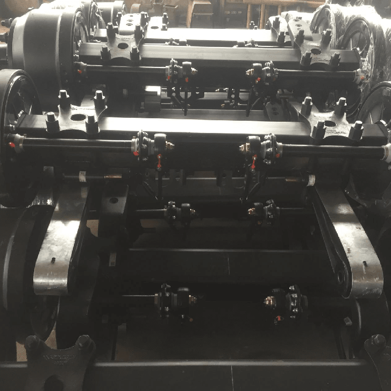
Connection mode 3: One piece support beam; place the support beam on the horizontal locating tooling. Setting the center distance of two support beam; Place the axle on the axle seat of the support beam, and place the camshaft on the right place. (subject to the confirmed technical drawings by two parties); Adjust the position of axle to the middle position of the Support beam, the error <=1mm; Lamp and fix the axle and the support beam to close the axle seat; Spot welding the axle and the support beam; Full welding the positions with 3 times. And 10mm height.
Notice: 1. The center of two axle sleeve shall be in the same straight line, while placing the supporting beam, and parallel to the axle center line;
2.When the axle is installed, at least one side of the supporting beam should be firmly closed with the axle beam in parallel. If the other side is not, the tilt gap may not exceed 2mm.
3.The 4 root welding seams of both sides of the supporting beam must been completely welded, then continue to weld the second and the third seam.
3.Installation of leaf spring (spring beam)
(1) Forward direction place the locating spacer (if has), leaf spring and guard plate (if has) in order into the clamping groove of upper plate;
Note: mount the locating hole of leaf spring into the locating pin of locating spacer.
(2) Mount the U bolt spacer, U bolt, gaskets and U-bolt nut successively; (it only needs to slightly tighten the nut before calibration)
(3) Welding adjust the center distance between the leaf spring (spring beam) center and axle center, with requirement: A=B+-1mm;
(4) Adjust the center distance of leaf spring within 1mm
(5) Spot weld and position the locking plate (if has) and support of leaf spring with welding height 5mm.
Note: Some products without locking plate no need spot welding
(6) Fasten the U-bolt nut into specified torque, the tighten torque is performed according to the provisions of P22 Torque Table for important fasteners;
(7) Check whether the relative position dimension between the leaf spring (spring beam) center and axle center meets the requirements; if not, adjust them according to the procedures mentioned above;
(8) Weld the locking plate and upper plate with welding height 5mm.
Auxiliary tooling installation of front hanger, shock absorber
A.Place front hanger; mount the wearing plate, adjusting gasket, leaf spring axle, gasket and nut successively; with the help of auxiliary tooling, when adjusting the front hanger to the mounting height;
Notice: 1. on the adjusting plate, the square hole orientation in vertical direction;
2.Before adjusting, push all the adjusting plate up to the top position;
A.Remove the auxiliary tooling; successively mount the shock absorber, shock absorber shaft, gasket and nuts; tighten up the shock absorber.
FAQ
Q1. What is your terms of packing?
A: Generally, goods are sealed in ploy bags and packed in cartons and pallet or wood cases.
Q2. What is your terms of payment?
A: T/T (deposit + balance before delivery). We’ll show you the photos of the products and packages before you pay the balance.
Q3. What is your terms of delivery?
A: EXW, FOB, CFR, CIF.
Q4. How about your delivery time?
A: Generally, it will take 25 to 60 days after receiving your advance payment. The specific delivery time depends on the items and the quantity of your order.
Q5. Can you produce according to the samples?
A: Yes, we can produce by your samples or technical drawings. We can build the molds and fixtures.
Q6. What is your sample policy?
A: We can supply the sample for free charge if we have ready parts in stock, but the customers have to pay the courier cost.
Q7. How do you make our business long-term and good relationship?
A: We provide our clients with one-stop service, from specific component to final assembled products, solving various problem for different clients all over the world.
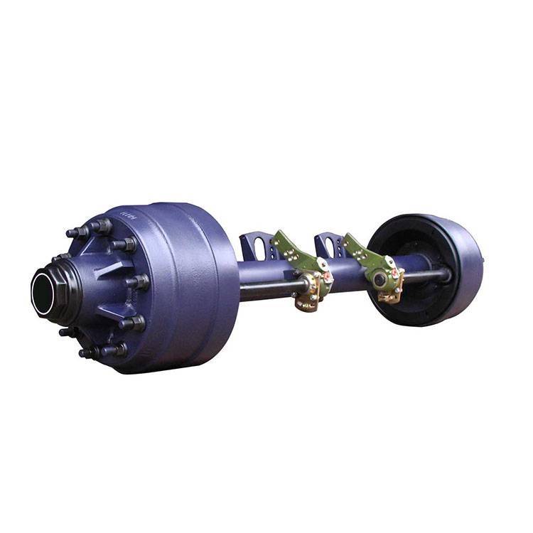
Product detail pictures:


Related Product Guide:
We insist on offering premium quality manufacturing with superior business concept, honest product sales as well as finest and fast assistance. it will bring you not only the good quality product or service and huge profit, but the most significant is to occupy the endless market for 2020 wholesale price Trailer Axle Bearings - How to install the air suspension on the axle – MBP , The product will supply to all over the world, such as: New Orleans, Guatemala, Sudan, our qualify products have good reputation from the world as its most competive price and our most advantage of after-sale service to the clients.we hope we can provide a safe, environmental products and super service to our clients from all of the world and establish strategic partnership with them by our professional standards and unremitting efforts.
We always believe that the details decides the company's product quality, in this respect, the company conform our requirements and the goods are meet our expectations.
